
AutoForma, unlike freeForma, will automatically model for you an already designed orthosis.
If you have classic pathologies to which a constant model corresponds, this is the tool for you. If, on the other hand, you wish to have more freedom in the creation of the brace via Freeforma, for example, to draw dimples on a scar or a sensitive area, you can follow our modeling guide via FreeForma.
With 4 steps, Autoforma will model the perfect orthosis for you in a few minutes.
The 4 steps process:
 |
 |
 |
 |
| Landmark positioning | Design customization | Thickness and offset options | Beltloops positioning |
1. Land mark positionning
 |
The first step is simply to place landmarks on the scan as in the scan correction step. |
2. Design customization
 |
The first step when having the template applied to the corrected scan is adapting the length of the device as well as the boundary width. The boundary width can be used to ensure enough space along the edges of the device to place the beltloop, but also to make sure the device is rigid enough to support the patients limb regardless of the alveoles. When 'pattern off' is enable, the alveoles will be closed. |
 |
The second step of the fitting is to adapt the alveole pattern. By clicking on one of the Alveoles you'll get the possibility to adapt the width and density of the alveoles. By adapting these parameters, you'll get the possibility to make the alveoles bigger or smaller, also leaving the device more flexible or rigid. |
 |
Lastly, before moving on to the finishing step, we'll have the possibility to adapt the trimlines. If you click on the trimlines (thick grey lines), small nodes will appear allowing you to modify the trimlines. It might take some time before the trimlines regenerate. |
3.Thickness and offset options
|
|
In this modeling stage, you will have four possibilities.
|


4.Beltloops positionning
|
The last step of the modeling process will be to position your beltloops on the brace. W also have the possibility to add rivet holes, mushroom pins as well as internal slotted holes. |
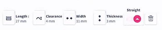
- Length: Adapt the length of the beltloop with the sliders, according to the width of the straps.
- Clearance: Adapt the height of the buckle to make sure the strap has enough space to go through the beltloop.
- Width: Make sur the beltloop is wide enough, so it is strong enough to close the device in a firm way.
- Thickness: Make sur the beltloop is wide enough, so it is strong enough to close the device in a firm way.
- Straight/curved toggle: Change the shape of your beltloop, make it straight or following the shape of the trimline.
- Trash Can: Delete this beltloop.
5. Engrave and export
|
If you are satisfied with your orthosis, you can now engrave a serial number on it and export it to your folder. Once you have clicked on the start button, you'll have the possibility to chose the text that needs to be engraved (max 11 characters long). You can then move this serial number on the orthosis by sliding it with your finger and repositioning it using the two rotation arrows. You can press on validate, to save your orthosis and export it. |
Once you have exported it, you will automatically be brought back to your new order. Beware, as of now, once you have exported your orthosis, you cannot further edit it.
Congratulations! You are now able to create easily a consistent orthosis that will be easily printable and ready out of the oven!